|
 |
||||||
|---|---|---|---|---|---|---|---|
| Laminar Flow Airfoil |
 |
 |
 |
 |
 |
||
 |
 |
 |
 |
 |
|||
 |
||
|
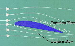
Laminar Flow is the smooth, uninterrupted flow of
air over the contour of the wings, fuselage, or other
parts of an aircraft in flight. Laminar flow is most
often found at the front of a streamlined body and is
an important factor in flight. If the smooth flow of
air is interrupted over a wing section, turbulence is
created which results in a loss of lift and a high
degree of drag. An airfoil designed for minimum drag
and uninterrupted flow of the boundary layer is called
a laminar airfoil.
The Laminar flow theory dealt with the development of a symmetrical airfoil section which had the same curvature on both the upper and lower surface. The design was relatively thin at the leading edge and progressively widened to a point of greatest thickness as far aft as possible. The theory in using an airfoil of this design was to maintain the adhesion of the boundary layers of airflow which are present in flight as far aft of the leading edge as possible. On normal airfoils, the boundary layer would be interrupted at high speeds and the resultant break would cause a turbulent flow over the remainder of the foil. This turbulence would be realized as drag up the point of maximum speed, at which time the control surfaces and aircraft flying characteristics would be affected. The formation of the boundary layer is a process of layers of air formed one next to the other, i.e.; the term laminar is derived from the lamination principle involved.
The History of Laminar Flow The North American P-51 Mustang was the first aircraft intentionally designed to use laminar flow airfoils. However, wartime National Advisory Committee for Aeronautics (NACA) research data shows that Mustangs were not manufactured with a sufficient degree of surface quality to maintain much laminar flow on the wing. The Royal Air Force (RAF) found that the Bell P-63 Kingcobra, despite being designed with laminar airfoils, also was not manufactured with sufficient surface quality to have much laminar flow. The Mustang was a mathematically designed airplane and the wing foil that was to be classified as a "semi-empirical venture" by the British was cleared for adoption on the new design. The wing section would be the only part of the fighter which would be tested in a wind tunnel prior to the first test flight. Due to the speculation of the success of the radical foil, the engineering department was committed to adopt a more conventional airfoil within thirty days of the tests in the event the wing did not come up to specifications. A one quarter scale model of the wing was designed and constructed for tests in the wing tunnel at the California Institute of Technology. The use of this airfoil on the Mustang would greatly add to the drag reducing concept that was paramount in all design phases of the airplane. The few applications of this foil, prior to this time, had been handbuilt structures which were finished to exacting tolerances. An absolutely smooth surface was necessary due to the fact that any surface break or rough protrusion would interrupt the airflow and detract from the laminar flow theory. Because of the exactness required, the foil had been shelved by other manufacturers due to the clearances and tolerances which are used in mass production. The engineers at North American Aviation (NAA) approached this problem with a plan to fill and paint the wing surface to provide the necessary smoothness. The foil which was used for the Mustang had a thickness ratio of 15.1 percent at the wing root at 39 percent of the chord. The tip ratio was 11.4 percent at the 50 percent chord line. These figures provided the maximum thickness area at 40 percent from the leading edge of the wing and resulted in a small negative pressure gradient over the leading 50-60 percent of the wing surface. The Consolidated B-24 Liberator "Davis" airfoil was also a laminar flow airfoil, which predates the Mustang's. However, the designers of the B-24 only knew that their airfoil had very low drag in the wind tunnel. They did not realize that it was a laminar flow airfoil. There were several aircraft modified by NACA, in the late 1930s, to have laminar flow test sections on their wings. Hence, such aircraft as a modified B-18 were some of the first aircraft to fly with laminar flow airfoils. The boundary layer concept is credited to the great German aerodynamicist, Ludwig Prandtl. Prandtl hypothesized and proved the existence of the boundary layer long before the Mustang was a gleam in anyone's eye.
Example: First, let's get more specific about what laminar flow is. The flow next to any surface forms a boundary layer, as the flow has zero velocity right at the surface and some distance out from the surface it flows at the same velocity as the local outside flow. If this boundary layer flows in parallel layers, with no energy transfer between layers, it is laminar. If there is energy transfer, it is turbulent. All boundary layers start off as laminar. Many influences can act to destabilize a laminar boundary layer, causing it to transition to turbulent. Adverse pressure gradients, surface roughness, heat and acoustic energy all examples of destabilizing influences. Once the boundary layer transitions, the skin friction goes up. This is the primary result of a turbulent boundary layer. The old lift loss myth is just that—a myth. A favorable pressure gradient is required to maintain laminar flow. Laminar flow airfoils are designed to have long favorable pressure gradients. All airfoils must have adverse pressure gradients on their aft end. The usual definition of a laminar flow airfoil is that the favorable pressure gradient ends somewhere between 30% and 75% of chord. Now consider the finish on your car in non-rainy conditions. Dust and leaves have settled on the hood's paint. We go for a drive. At once the leaves blow off. But the dust remains. We speed up. Even if we go very fast, the dust remains because of the thin layer of air that moves with the car. If you drive with dew on your car, the dew will not so quickly be blown dry where the air flow has this thin laminar layer. Downstream, where the laminar flow has become turbulent, the air flow quickly dries the dew. In the fifties this was dramatically shown in a photograph of the top of a sailplane wing (in-flight) that had dew on it. A few tiny seeds had landed on forward area the wing while on the ground. In flight these seeds, tiny though they were, reached through the laminar layer and caused micro-turbulence causing the dew to be blown dried in an expanding vee shaped area down stream of each tiny seed.
Additional information Profile drag This comprises two components: surface friction drag and normal pressure drag (form drag). Surface friction drag: This arises from the tangential stresses due to the viscosity or stickiness of the air. When air flows over any part of an aircraft there exists, immediately adjacent to the surface, a thin layer of air called the boundary layer, within which the air slows from its high velocity at the edge of the layer to a standstill at the surface itself. Surface friction drag depends upon the rate of change of velocity through the boundary layer, i.e. the velocity gradient. There are two types of boundary layer, laminar and turbulent. Although all combat aircraft surfaces develop a laminar boundary layer to start with, this rapidly becomes turbulent within a few per cent of the length of the surface. This leaves most of the aircraft immersed in a turbulent boundary layer, the thickness of which increases with length along the surface. The velocity and hence pressure variations along the length of any surface can have adverse effects on the behavior of the boundary layer, as will be discussed later. Surface friction drag can amount to more than 30% of the total drag under cruise conditions. Normal pressure drag (form drag): This also depends upon the viscosity of the air and is related to flow separation. It is best explained by considering a typical pressure distribution over a wing section, first at low Angle of Attack (AOA) and then at high AOA. At low AOA the high pressures near the leading edge produce a component of force in the rearward (i.e. drag) direction, while the low pressures ahead of the maximum thickness point tend to suck the wing section forward, giving a thrust effect. The low pressures aft of the maximum thickness point tend to suck the wing rearwards, since they act on rearward-facing surfaces. Without the influence of the boundary layer, the normal pressure forces due to the above drag and thrust components would exactly cancel. There is a favorable pressure gradient up to the minimum pressure point, with the pressure falling in the direction of flow. This helps to stabilize the boundary layer. Downstream of the minimum pressure point, however, the thickening boundary layer has to flow against an adverse pressure gradient. Viscous effects reduce momentum within the boundary layer, and the thickness of the layer further increases so that the external flow sees a body which does not appear to close to a point at the trailing edge. A narrow wake is formed as the boundary layer streams off the section. This prevents the pressures on the aft-facing surface of the wing section from recovering to the high value obtaining near the stagnation point on the leading edge, as they would have done if a boundary layer had not formed. There is thus a lower than expected pressure acting on the aft facing surface, giving rise to normal pressure drag. In the low-AOA case this component is small, most of the profile drag being made up of surface friction drag. As the AOA of the wing section is increased, the point of minimum pressure moves towards the leading edge, with increasingly high suction being achieved. This means that the pressure then has to rise by a greater extent downstream of the minimum pressure point and that the length of wing surface exposed to the rising pressure is increased. The resulting adverse pressure gradient becomes more severe as AOA is increased. This has serious implications for the boundary layer, which is always likely to separate from the wing surface under such conditions. |
Return to Aircraft Theory Index
© The Aviation History Online Museum. All rights reserved.
Created June 3, 2002. Updated June 1, 2015.